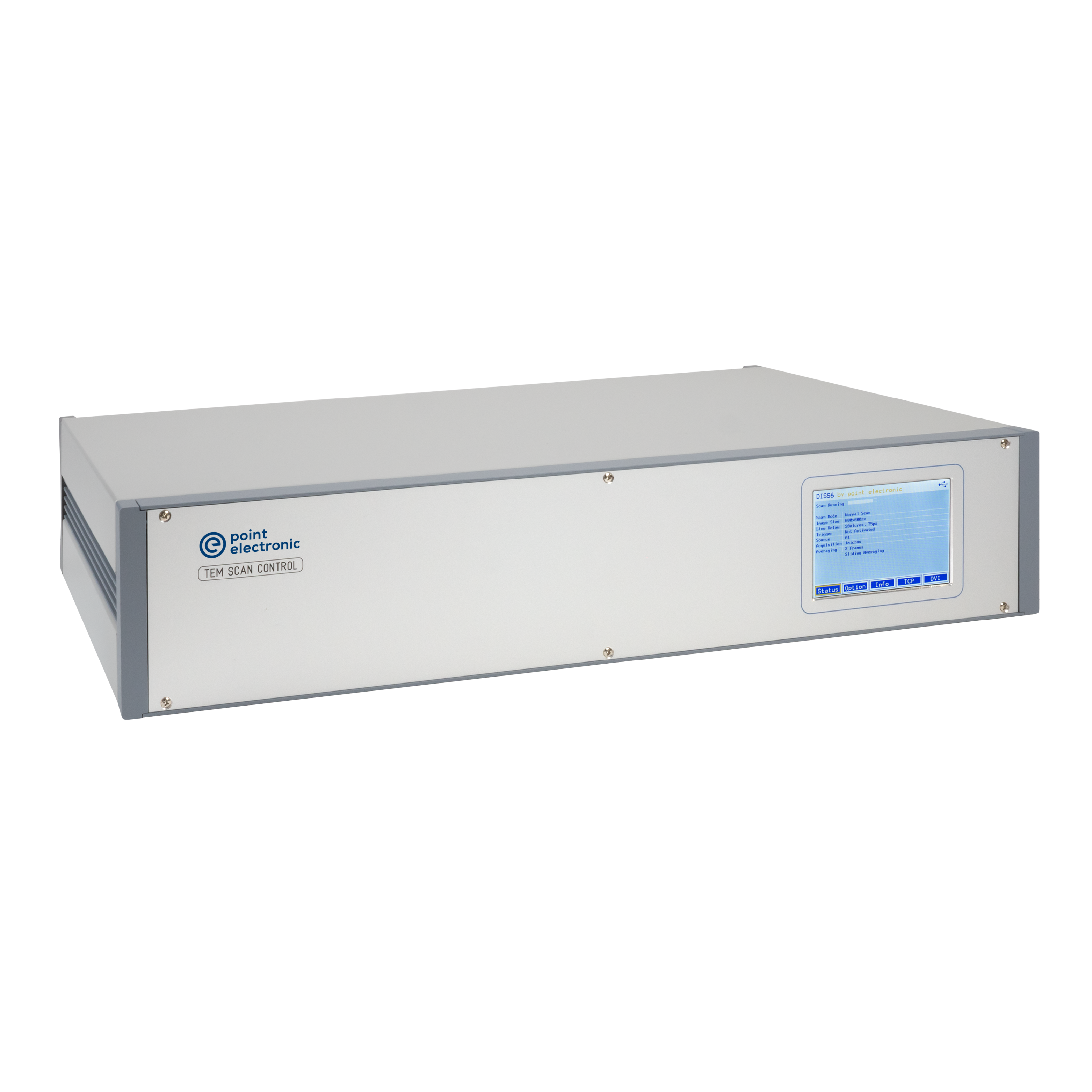
TEM Scan Controller
The TEM Scan Controller is an external scan controller based on our high-performance Digital Imaging Scanning System scan engine. It is specifically prepared for researchers, developers or SMEs that require independent equipment or technique development in TEM.
It is designed for, and tested, on all major TEM manufacturer external scan interfaces, and connects to a PC or laptop over a USB or ETH interface. Its control library is easily integrated in new Windows and Linux software* - sample code is provided for Python, C and C#. Full hardware control is given, with the API documentation, over conventional image scans, as well as pixel map scans and hardware syncronisation with 4D STEM detectors and imaging cameras.
Signal inputs include analog channels for conventional BF, HAADF and similar detectors, as well as digital channels for pulse processors.
Key features:
- Control display, designed for independent development and service
- Scan Signals: Analog outputs for all major TEM external scan interfaces
- Detector signals: Analog inputs for standard BF and HAADF detectors
- Control Interfaces: Standard control and data interfaces, for Windows and Linux
- Pulse signals: Digital inputs for pulse processors with single electron counting
- Synchronisation: Adjustable TTL trigger inputs and outputs for 4D STEM cameras
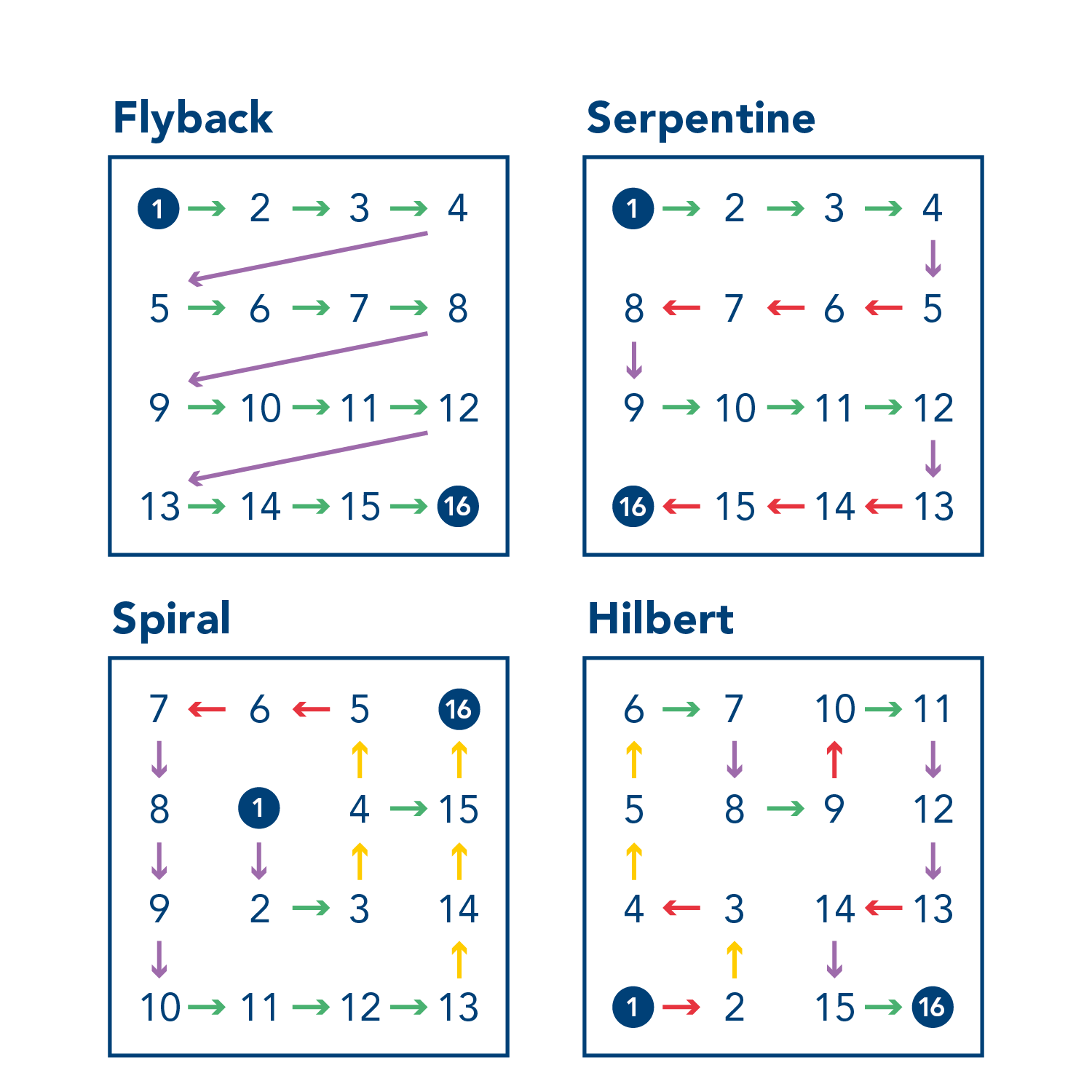
Advanced scan patterns - pixel maps
- Prepare a list of coordinates and times
- Upload to the scan controller
- Run and download digitized values
- Build an image, display on screen, repeat
* Service app supplied with the hardware is for Windows 11...7
Standard inputs
- 2x4 calibrated analog inputs (A1…A4, B1…B4)
- 12x digital inputs (D1…D12)
- 3x trigger inputs (Pixel, Line and Frame)
- Pause/resume input
Standard outputs
- 2x calibrated analogue scan outputs (X, Y)
- 2x calibrated analogue magnification outputs (X, Y)
- 2x external control outputs (Blank and Scan)
- 4x clock outputs (Pixel, Line, Frame and Blank)
Control interfaces
- USB2
- ETH
Scan modes
- Sawtooth scan mode
- Pixel map mode
- Chopped scan mode
- Subpixel scan mode
Scan generator
- 16-bit ±3.5…±12V analog X, Y scans (unbalanced)
- 16-bit, +-2.2V…7.5 (+-0.65… 2.2V) analog X, Y scans (balanced)
- 16-bit 3.5…12V analog X, Y magnifications
- 10-bit ±1.8V analog X, Y shifts
- Gnd., 5V, 15V external bank/scan
- TTL pause/resume
- TTL clock and synchronization
- 0.5 GPixels maximum frame size (software limit)
- 10 ns…10 s pixel dwell time (selection dependent)
- 0…256× frame average
- 0…50× line average
- Mains frequency synchronization
Signal digitization
- 12-bit for analogue A1..A4, B1...B4
- 16-bit for TTL D1...D12
- 32-bit for TTL D1...D6 (optional)
Touch display
- Scan status overview
- Installed options list
- Scan detailed information
- ETH connections settings
- DVI output settings
Electron counting (optional)
- 2x counter inputs (ECL1...ECL2)
- 2x threshold level outputs
- 1 GHz bandwidth
Lock-in amplifier (optional)
- 1x calibrated analogue input (LIA)
- TTL reference frequency output
- 20-bit digitization
- 1 μs...10 seconds pixel dwell time
MICS amplifier (optional)
- 16x calibrated inputs (M1…M16) maximum
- -1…1 V input offset M1…M16
- 1x … 1,800x gain M1….M16
- -1…1 V output offsets M1…M16
- 3.4 MHz…34 Hz low-pass filter
- 4x averages M1…M4, M5…M8, M9…M12, M13…M16
- Automated 4Q global brightness and contrast
- Automated input offsets (dark correction)
- Automated gain normalization (bright correction)
- Automated low-pass filter (matching pixel dwell time)
Housing
- 19-inch rack-mountable
-
TEM Scan Controller
-

-
Advanced scan patterns