DISS6 SEM Scan Controller
The most powerful and versatile scan generator and image acquisition system
DISS 6 - our Digital Image Scanning System generation 6 - is the highest performance and most versatile scan generator for
- active controlled, completely flexible scanning, and
- synchronized data and image acquisition
- for all scanning systems
- integrated in one device
Default app for independent use is the DISS6 image acquisition software.
✅ Highest image resolution: up to 500 mpx, flexible from 1 px
✅ Ultra-fast scanning speed: down to 10 ns dwell time, flexible from 500 ms
✅ Simultaneous acquision: of up to 20 signals, flexibly analog and digital, including single electron counting and lock-in amplification signals
✅ Versatile triggers and synchronization: pixel, line, frame, or beam blank control; operates as master (active scan generation with synchronized acquisition) or slave (external trigger input)
✅ Broad compatibility for all scanning devices: ion beam, electron beam, laser scanning, or gamma emitter
DISS6 image scanning is a core component in a wide range of techniques.
Built for versatile use cases
One controller, multiple signals, flexible possibilities - DISS 6 can be used for various constellations. Here are some examples:
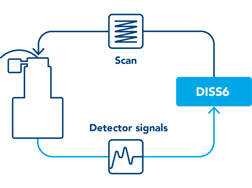
DISS 6 for standard SEM
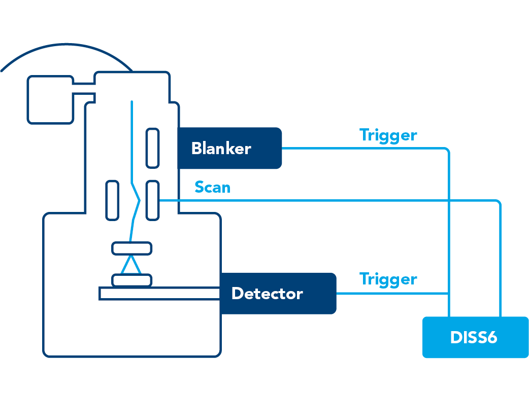
DISS 6 for 4D STEM synchronization
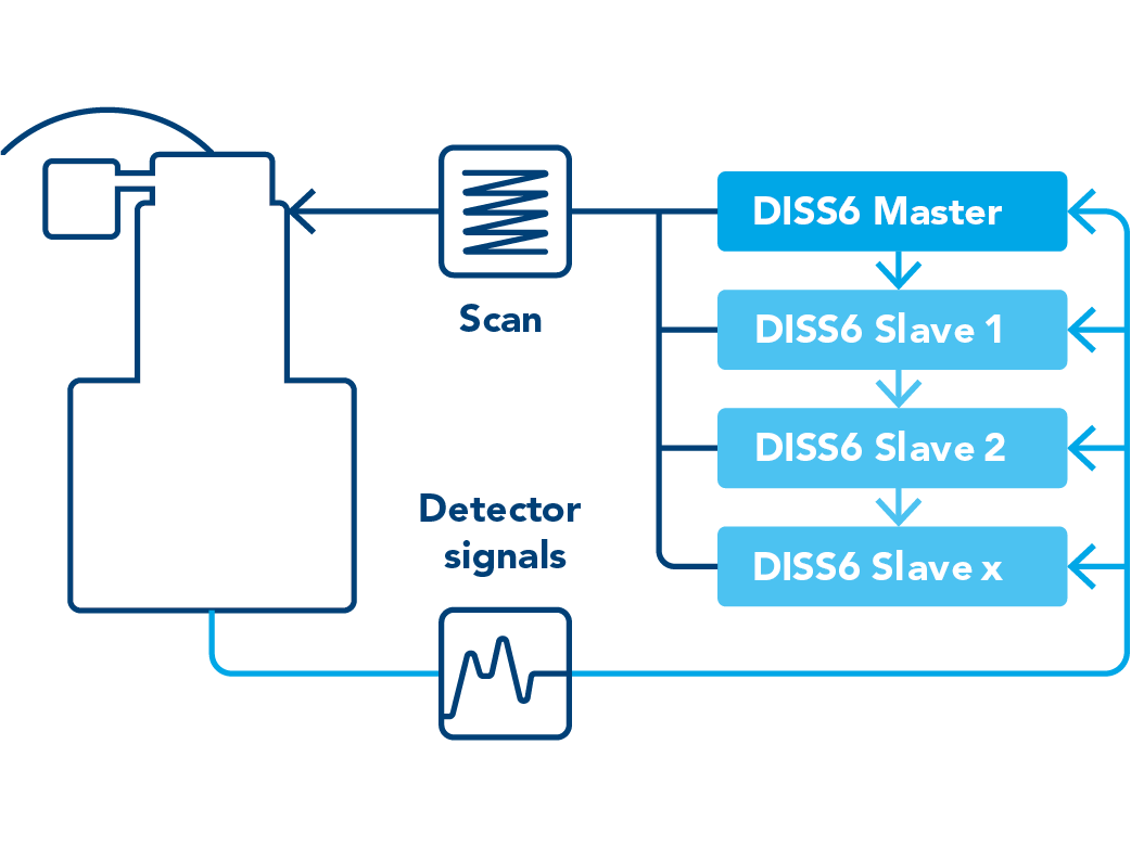
DISS 6 for 1...100+ channels
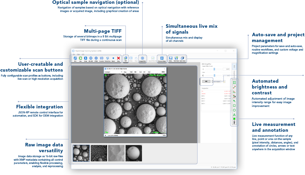
Full control of all scan and imaging parameters
DISS 6 software allows universal control and customization.
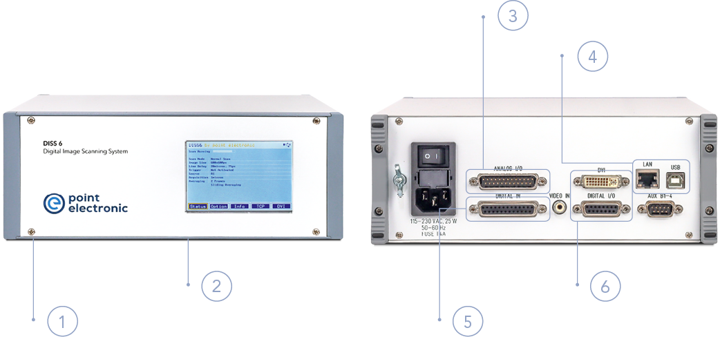
Full-featured scan generator and image acquisition
Digital Imaging Scanning System (DISS) can simultaneously acquire 4 analog and 12 digital inputs, expandable by up to 16 additional analog inputs via optional MICS amplifier.
1. Digitization of analog image signals (SE, BSE, CL, EBIC, EBAC)
2. Connection via SEM's external scan interface, and compatible with all major scanning microscope models
3. Synchronized multi-channel acquisition of ultra-fast and slow analog inputs with 12-bit digitization
4. Seamless network integration via TCP/IP and USB interfaces, with automated scan switch
5. Simultaneous 100 MHz digital counter inputs
6. Adjustable TTL trigger inputs, and clock outputs for synchronization with cameras or detectors
Open system architecture for maximum OEM integration
Engineered for seamless integration into OEM plattforms, combining open interfaces, scalability, and flexible customization.
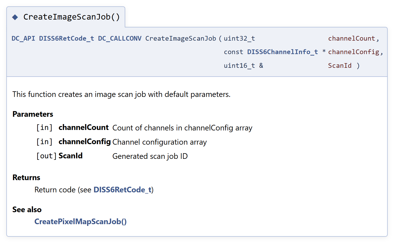
Custom software integration
- Software Development toolKit (SDK) for development of custom software, including access to all hardware functions, API, demo applications and DLL control library
- JSON-RPC remote control interface for seamless integration with any system
- Custom software branding
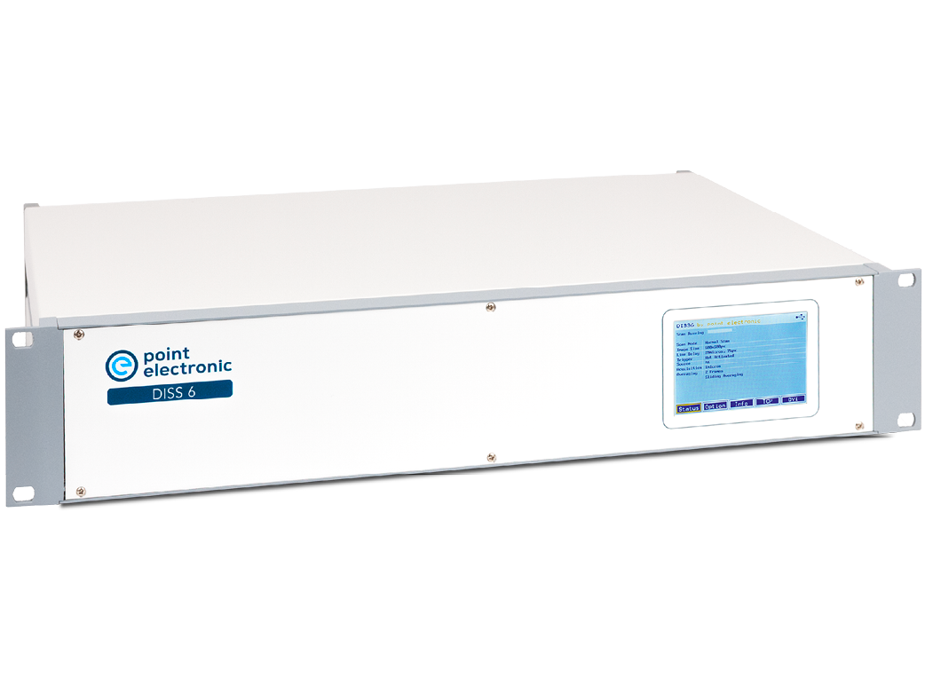
Custom hardware integration
- Custom housing branding
- Scalable form from board-level integration to 19-inch rack-mount systems
- Secure TCP/IP connectivity across modern and legacy microscope systems

Electron Beam Induced Current (EBIC)
- map internal electric fields in semiconductors and ceramics
- characterise electrical activity of defects
- localise material and/or processing defects

Resistance Contrast Imaging (EBAC/RCI)
- localise open and shorts in inteconnects
- identify weaknesses in oxide layers
- map resistance with high spatial resolution

Electron Beam Induced Current Change (EBIRCh)
- localise defects in transistors with high-spatial resolution
- pin-point leackages/weknesses in oxides
- similar with Optical Beam Induced Resistance change (OBIRCh)

Quantitative BSE (qBSE)
- map density with high-spatial resolution
- characterise distribution of phases
- reveal crystallography with orientation contrast

BSE Topography
- analyse 3D surfaces and complex surfaces
- monitor in-situ reactions, including high-temperature
- characterise milling and depoisition in FIB-SEM

3D scanning in SEM
- obtain 3D models of microscopic objects
- characterise distribution complex surfaces
Standard inputs
- 8× calibrated analogue inputs (A1...A4, B1...B4)
- 12× digital inputs (D1...D12)
- 3× trigger inputs (Pixel, Line and Frame)
- scan pause/resume input
Standard outputs
- 2× calibrated analogue scan outputs (X, Y)
- 2× external control outputs (Blank and Scan)
- 4× clock outputs (Pixel, Line, Frame and Blank)
- DVI display output
Control interfaces
- USB2
- TCP/IP
Scan modes
- Sawtooth scan mode
- Vector scan mode (with optional SDK)
- Chopped scan mode (with optional SDK)
- Subpixel scan mode (with optional SDK)
Scan generator
- 16-bit ±3.5...±12V analogue X, Y scans
- 16-bit 3.5...12V analogue X, Y magnifications
- 10-bit ±1.8V analogue X, Y shifts
- Gnd., 5V, 15V external bank/scan
- TTL pause/resume
- TTL clock and synchronisation
- 0.5 GPixels maximum frame size (software limit)
- 10 ns...500 ms pixel dwell time (selection dependent)
- 0...256× frame average
- 0...50× line average
- 1...32,000× pixel average (oversampling)
- Mains frequency synchronization
Signal digitization
- 12-bit for analogue A1..A4, B1...B4
- 16-bit for TTL D1...D12
- 32-bit for TTL D1...D6 (optional)
Electron counting (optional)
- 2× counter inputs (ECL1...ECL2)
- 2× threshold level outputs
- 1 GHz bandwidth
CCD-video input (optional)
- 1x PAL video input
Lock-in amplifier (optional)
- 1× calibrated analogue input (LIA)
- TTL reference frequency output
- 20-bit digitisation
- 1 μs...10 milliseconds pixel dwell time
MICS amplifier (optional)
- 16× calibrated inputs (M1...M16) maximum
- -1.25...1.25 V input offset M1...M16
- 1× ... 3,200× gain M1....M16
- -1...1 V output offsets M1...M16
- 3.4 MHz...34 Hz low-pass filter
- 4× averages M1...M4, M5...M8, M9...M12, M13...M16
- Automated 4Q global brightness and contrast
- Automated input offsets (dark correction)
- Automated gain normalisation (bright correction)
- Automated low-pass filter (matching pixel dwell time)
Touch display
- Scan status overview
- Installed options list
- Scan detailed information
- TCP connections settings
- DVI output settings
Housing
- 9.5-inch desktop
- 19-inch desktop (optional)
- 19-inch rack-mountable (optional)
Housing
- 19-inch rack-mountable
Software
DISS6 imaging control
- Configurable scan profiles
- Signals, pixel size, speed, averaging, sync
Image file formats
- TIFF (8 / 16 bit, grayscale / RGB), JPG
Inspector tool
- Automatic quantification of pixel values
- Editable formula files
Software Development toolKit (SDK) (optional)
- Windows and Linux control libraries
- Library API documentation
- DLL control library
- Demo applications
-
DISS6 image scanning

-
